Introduction to Pressure Ratings
To be used in pressure piping systems, every material must empirically prove its pressure bearing capability. This ensures that plants and facilities are integrating piping that can stand up to the long-term strength demands of their applications.
ASTM, ISO and the Plastic Pipe Institute Hydrostatic Stress Board have developed a number of test methods to verify the long-term hydrostatic strength (LTHS) of thermoplastic compounds (e.g. chlorinated polyvinyl chloride (CPVC)). These methods incorporate design factors which ensure that adequate material strength is reserved for factors besides pressure bearing, such as stresses related to installation, lot-to-lot variability, and chemical exposure.
Calculating the pressure rating is not as easy as increasing the pressure in a pipe till it bursts. Short-term tensile strength tests are not good indicators of a thermoplastic’s long-term strength, as they are with metals. For this reason, plastic piping LTHS is determined by analyzing stress versus time-to-rupture (that is, stress-rupture) test data. This data covers a testing period of no less than 10,000 hours, and is derived from sustained pressure testing of pipe made from the subject material.
Standard Thermoplastic Testing Methodology
There are two primary methods to determine a piping material’s long-term hydrostatic strength. The ASTM D2837, “Standard Test Method for Obtaining Hydrostatic Design Basis for Thermoplastic Pipe Materials or Pressure Design Basis for Thermoplastic Pipe Products” is the most commonly used in the United States. The other is ISO 9080, which you can read about here.
The ASTM methodology involves the following steps:
- Define the material’s Long-Term Hydrostatic Stress (LTHS) value.
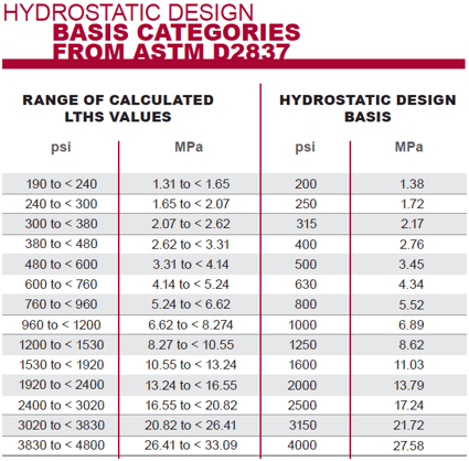
- Use its LTHS value to identify the material’s Hydrostatic Design Basis (HDB) category.
- Multiply the HDB by a design factor to come up with the material’s Hydrostatic Design Stress, or maximum allowable stress.
Let’s walk through how these values are calculated according to this standard.
Important Note: ASTM D2837 does not define a pressure rating for the pipe itself, but rather the long-term hydrostatic strength of the thermoplastic material. At the end of this post, we’ve included the formula that’s used to find a pipe’s pressure rating.
How to Calculate Long-Term Hydrostatic Strength
As mentioned previously, LTHS is determined by analyzing stress versus time-to-rupture (that is, stress-rupture) test data.
To determine CPVC’s LTHS value, pipe specimens made of the material are tested at various stress levels. Stress levels are chosen which will cause the pipe to rupture at time periods distributed over the range from 10 hours to more than 10,000 hours. For a pressure rating at 180°F, test times are required by PPI to exceed 16,000 hours.
The stress versus time-to-failure data are then plotted on a log/log scale where they should form a straight line which can be fit by linear regression analysis. The line is then extrapolated to determine the stress level which would result in a 100,000-hour rupture time.
When the data are in fact linear on a log/log scale, it is a generally accepted practice to extrapolate one log unit past the longest data point. (i.e., 1000 hours can be extrapolated to 10,000; or 10,000 hours can be extrapolated to 100,000.)
In most cases, the extrapolated stress level at 100,000 hours is used as the material’s Long Term Hydrostatic Strength (LTHS) value. In some cases, the results of statistical data validation (discussed below) may require that the extrapolated stress level at 50 years be used as the material’s LTHS value.
Validating the Data
To ensure the 100,000-hour strength is appropriate and reliable, there are a few validation mechanisms worked into the methodology:
- Calculate two-sided lower confidence limit (LCL): The lowest data points on the stress vs. time scatter point graph are analyzed by linear regression to determine the LCL value. If this value is not within 15 percent of the LTHS value, the data is considered unusable.
- Calculate 50-year strength: The LTHS data is also used to calculate a 50-year strength value. If this value is less than 80 percent of the 100,000-hour strength value, the 50-year value is used to determine the Hydrostatic Design Basis. This helps to account for materials with steeper regression slopes.
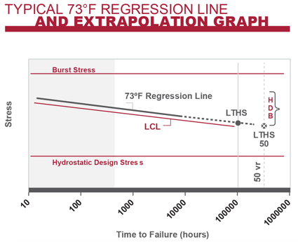
Typical 73°F regression line and extrapolation graph.
For piping materials, such as Polyethylene (PE), that may undergo oxidative failure, an additional validation is required to ensure that the 10,000-hour strength value can be reliably extrapolated to 100,000 hrs. This is not necessary for CPVC.
Once the LTHS value has been determined by regression analysis and statistical validation, the materials Hydrostatic Design Basis (HDB) is determined by categorizing the LTHS value as defined in ASTM D2837.
Using Design Factor to Calculate Hydrostatic Design Stress
The hydrostatic design basis (HDB) category is a measure of the material's ultimate strength performance, but in real-world industrial applications it is important to account for the fact that internal stress won’t be the only variable that can affect long-term performance.
For this reason, the Hydrostatic Design Board decided by consensus that a material’s HDB value should be multiplied by a design factor to determine the material’s maximum allowable pressure stress, or hydrostatic design stress (HDS).
This design factor is based on two groups of variables:
- Manufacturing and testing variables, specifically: normal variations in material, manufacture, dimensions, good handling techniques, and evaluation processes.
- Application and use variables, specifically: installation, environment, temperature, hazard involved, life expectancy desired, and degree of reliability selected.
For water applications, it was determined that a design factor of 0.5 should be applied to CPVC piping to account for these variables. For chemical processes, an engineer may decide to apply a design factor less than 0.5 based on the process demands.
Pipe Pressure Rating
The preceding is designed to calculate the maximum allowable stress for a piping material, not the actual pipe itself. To define a pipe’s pressure rating, the pipe’s diameter and wall thickness need to also be taken into account.
A piping material’s HDS is plugged into the following equation to define a pipe’s pressure rating:
S = P (D-t) / (2t)
Or
S = P (d+t) / (2t)
Where:
- S = Stress
- P = Pressure
- D = Average outside diameter
- d = Average inside diameter
- t = Minimum wall thickness
For example …
4” Corzan® type 4120 schedule 80 pipe at 73°F
2000 [psi] = P * (4.5 [in] – 0.337 [in]) / (2 * 0.337 [in])
P = 324 [psi] ≈ 320 [psi] at 73°F
4” Corzan® type 4120 schedule 80 pipe at 180°F
500 [psi] = P * (4.5 [in] – 0.337 [in]) / (2 * 0.337 [in])
P = 81 [psi] ≈ 80 [psi] at 180°F
The value derived from this formula is the pressure rating you’ll see printed on the side of a pipe. It is based on the pipe’s performance at 73°F in a water application.
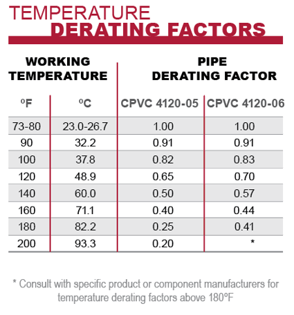
Working at Other Temperatures
The pressure ratings for CPVC pipes have been empirically determined according to the above-outlined methods at 73°F and 180°F. When operating at other temperatures, the derating factors supplied in ASTM F441 should be applied by the system design engineer. Temperature derating factors for pipe are obtained by interpolating the ratings at 73°F and 180°F. There are no “uprating” factors for working at temperatures lower than 73°F. In that situation, the 73°F rating should be used.
Please note: This derating factor is in addition to the design factor (0.5), which is already accounted for.
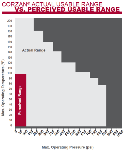
Use Your Discretion
Ultimately, a pipe’s pressure rating is a guideline, and plant engineers should fully assess the demands of their piping system before choosing a material.
Specifically, consider maximum operating temperature, temperature differential, external pressures, chemicals, external stress and UV exposure. Depending on your application, apply your own design factor rating to further safeguard your system from ruptures.
For More Information
If you have questions, or are interested in how to account for pressure rating in your industrial design, please contact our team of product and engineering experts. We’re always available to chat.
Ready to Get Started?
Contact us for a free process suitability and technical consultation. We want to make sure you get the localized support and information you need to take your project from blueprint to completion.