When designing an industrial piping system, it’s important to know the carrying capacity and friction loss for the piping material. The tables at the bottom of this page detail this information for Corzan® CPVC Schedule 40 and 80 piping. The formulas that explain how these values were calculated are below.
Linear Velocity of Fluid Flow
The linear velocity of a flowing fluid in a pipe is calculated from:
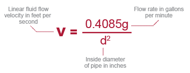
The values in the table below are accurate for all fluids.
Linear fluid flow velocity in a system should generally be limited to 5 ft./s. for industrial applications, particularly for pipe sizes 6-in. or greater.
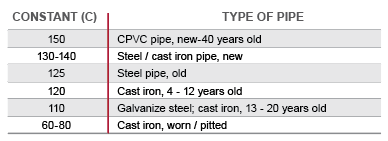
Hazen-Williams C Factor
A great advantage Corzan piping enjoys over metallic pipe is a smooth inner surface, which is resistant to scaling and fouling. This means that friction pressure losses in the fluid flow are minimized from the beginning and do not significantly increase as the system ages, as can be the case with metal pipes subject to scaling.
The Hazen-Williams formula is the generally accepted method of calculating friction head losses in piping systems. The friction head loss values in the fluid flow tables below are based on this formula, and Corzan CPVC piping’s surface roughness constant of C = 150.
For reference, the surface roughness constants for both new and old piping materials are given below.
Piping Friction Head Loss
The flow characteristics of water flowing through piping systems are affected by several factors including system configuration, pipe size and length, friction at the pipe and fitting surfaces, etc.
These and other factors cause a reduction in pressure (head-loss, also expressed in pressure drop) over the length of the system. This section deals only with the head-losses that result from frictional forces in various sizes of Corzan CPVC pipe and fittings.
The following formula was used to calculate water velocities, head-losses and pressure drops as a function of flow rates. The results are given in the tables below for both Schedule 40 and 80 piping. The Hazen-Williams formula can be used to adequately describe these losses.
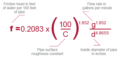
One foot of water = 0.4335 psi
Fittings Friction Head Loss
Friction losses through fittings are calculated from the equivalent length of straight pipe that would produce the same friction loss in the fluid. The equivalent lengths of pipe for common fittings are given below:
Equivalent Length of Pipe (feet)
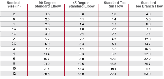
The data provided in this table is for reference only. Consult the fitting manufacturer’s literature for additional information.
Valves and Strainers Friction Head-Loss
Pressure drop in valves and strainers is calculated using flow coefficient values, which are published by the valve manufacturer. The equation for calculating pressure drop in this manner is:
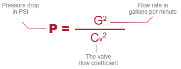
Typical flow coefficients for different valves and strainers can be found in the valve/strainer manufacturer’s literature. Pressure drops for fluids other than water may be calculated by multiplying the value calculated from the above equation by the specific gravity of the fluid.
Maximum Surge Pressure – Water Hammer
Whenever a flow rate of a fluid in a pipe is changed, there is a surge in pressure known as water hammer. The longer the line and faster the fluid is moving, the greater this hydraulic shock will be.
Water hammer may be caused by opening or closing a valve, starting or stopping a pump, or the movement of entrapped air through the pipe.
The maximum water hammer surge pressure may be calculated using the following formula:
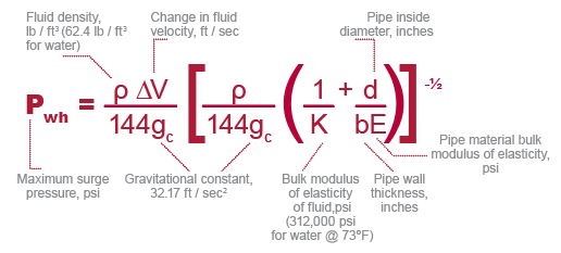
The values in the following fluid flow tables are based on this formula at 73°F (23°C) with the assumption that water flowing at a given rate of gallons per minute is suddenly and completely stopped. At 180°F (82.2°C), the surge pressure is approximately 15% less. The value for fluids other than water may be approximated by multiplying by the square root of the fluid’s specific gravity.
THE WATER HAMMER SURGE PRESSURE PLUS THE SYSTEM OPERATING PRESSURE SHOULD NOT EXCEED 1.5 TIMES THE RECOMMENDED WORKING PRESSURE RATING OF THE SYSTEM.
In order to minimize hydraulic shock due to water hammer, linear fluid flow velocity should generally be limited to 5 ft./s., particularly for pipe sizes of 6-in. or larger. Velocity at system start-up should be limited to 1 ft./s. during filling until it is certain that all air has been flushed from the system and the pressure has been brought up to operating conditions.
Air should not be allowed to accumulate in the system while it is operating. Pumps should not be allowed to draw in air.
Where necessary, extra protective equipment may be used to prevent water hammer damage, which might include pressure relief valves, shock absorbers, surge arrestors, and vacuum air relief valves.
BIM Object Library
To simplify the process of integrating Corzan® CPVC pipe, fittings and valves into your industrial plant CAD designs, we’ve made our library of BIM objects and specifications available for download.


Corzan® CPVC Chemical Resistance Table
Curious if Corzan® CPVC can stand up to the demands of your chemical processes? This table lists Corzan CPVC’s compatibility with more than 400 chemicals and compounds.

Ready to Get Started?
Contact us for a free process suitability and technical consultation. We want to make sure you get the localized support and information you need to take your project from blueprint to completion.
