

Read the full post below or check out the Thermal Expansion Infographic for a snapshot overview of this blog post.
All material has inherent thermal properties that affect its characteristics depending on the amount of heat or cold it’s exposed to. The more heat is applied, the more materials tend to expand and soften. The colder the conditions, the more materials tend to contract and harden.
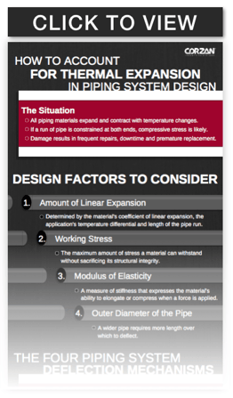
In the case of piping systems, we are most concerned with linear expansion and contraction, which affects both metallic and thermoplastic piping materials. Piping system design must consider thermal expansion because temperature changes cause piping materials to expand and contract. If this change in size isn't accounted for in design, the system can be damaged by normal working conditions, which can lead to leaks and even failure. This is especially true for industrial plant systems, which often subject pipe to extreme temperatures and pressures.
For example, if a run of pipe is constrained at both ends, as it heats up linear expansion will cause compressive stress on the material. When this undue force exceeds the allowable stress on the material, it will result in damage to the pipe and potentially brackets, fittings, and valves.
Depending on the scope of that damage, plants may be forced to conduct frequent repairs, shut down processes, and potentially replace the piping system prematurely.
Fortunately, while expansion and contraction are unavoidable, resultant issues can be easily circumvented with the proper design considerations. Thermal expansion in a piping system is accommodated in the design phase through various deflection mechanisms, including expansion loops, expansion offsets, changes of direction and expansion joints.
Before we explain how to deploy each mechanism, we need to look at the four factors that influence their design.

Design Factors to Consider
1. Amount of Linear Expansion
The amount a pipe will expand and contract is dependent on three factors:
Coefficient of Linear Expansion
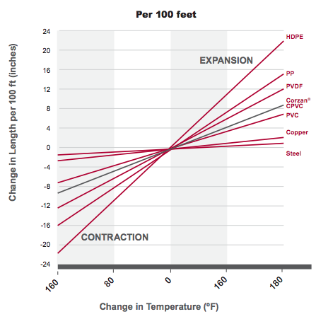
Every material has a coefficient of linear thermal expansion, which simply says per degree of temperature change you’re going to have X amount of linear expansion. There are empirical tests run on all piping material to determine this coefficient.
In the chart below, you can see the amount different piping materials change in length as the temperature changes.
Temperature Differential
Temperature differential is the temperature range the pipe will be exposed to. In other words, the difference between the coldest and hottest the pipe will be from time of installation through its service life. To determine your pipe’s temperature differential, consider the following:
- What is the temperature at installation? In a conditioned space, this may be one of the extreme temperatures it will reach.
- What is the temperature of the fluid flowing through the pipe, and will that fluid temperature be constant?
- If the pipe is outdoors, what is the seasonal climate change?
Length of Pipe
The longer the pipe run, the more it will expand or contract. Essentially, every additional foot of material has an additive effect on how long the pipe will expand or contract.
2. Working Stress
Working stress is the maximum amount of stress a material can be subjected to when in use. All piping material can withstand some degree of movement without sacrificing its structural integrity.
3. Modulus of Elasticity
The modulus of elasticity is a measure of stiffness. It is an intrinsic property of the pipe material that expresses the material’s ability to elongate or compress when a force is applied.
4. Outer Diameter of the Pipe
The outer diameter of the pipe affects the ability of the pipe to deflect stress. For example, a CPVC pipe run of 100 feet subjected to a max. temperature of 120°F and a min. temperature of 80°F will expand 1.6 inches, no matter the outer diameter of the pipe. But, a 1-in. pipe can deflect more stress than a 6-in. pipe, so the deflection mechanism (total loop length) only needs to be 2.47 ft. long for a 1-in. pipe. In the same situation, a 6-in. pipe will need a deflection mechanism 5.55 ft. long.
The Four Piping System Deflection Mechanisms
Depending on the area through which a pipe will run, engineers have four deflection mechanism options to use to account for thermal expansion and contraction. Each allows for some degree of pipe movement to help prevent compressive stresses.
To help illustrate each mechanism, we included a pipe-run scenario with the following dimensions:
- Pipe material: CPVC
- Pipe diameter: 4-in.
- Pipe-run: 100 feet
- Temperature differential: 40°
- Maximum temperature: 120°F
- Minimum temperature: 80°F
For this situation, the linear expansion of the pipe is 1.6 in.
1. Expansion Loop
This mechanism tends to be the preferable choice of engineers.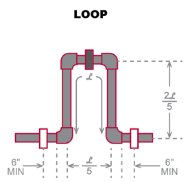
How it works: In the middle of a run of pipe, a “U” is configured and its center is restrained with a bracket. Each side of the pipe run coming into the U is hung with a hanger or guide, which allows the pipe to move back and forth. As the pipe expands, the opening of the U narrows, and with pipe contraction the U opening widens.
Using the example and provided image: L represents the total length of the loop, with 2/5L representing each vertical portion, and 1/5L representing the horizontal cross section where the restraint is placed.
- L = 54.8 in.
- 1/5 L = 11.0 in.
- 2/5 L = 21.9 in.
2. Expansion Offset
This mechanism is used when the pipe needs to avoid fixed structures.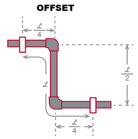
How it works: Placed in the center of a pipe run, each elbow allows for some degree of deflection as does the vertical length of pipe. The end of each pipe run is set using hangers or guides positioned a defined distance from the elbow. Using the diagram above, as the pipe expands, the top and bottom elbows will push in, causing the vertical length to angle to the right. With contraction, the vertical pipe will angle to the left.
Using the example and provided image: L represents the total length of the offset from the hanger or guide on one end to the opposite one. 1/4L signifies the distance from the hanger or guide to the closest elbow. 1/2L represents the perpendicular section of pipe.
- L = 54.8 in.
- 1/4 L = 13.7 in.
- 1/2 L = 27.4 in.
3. Change of Direction
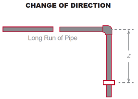
All piping system naturally include changes in direction, which can also be used as deflection mechanisms.
How it works: At the end of the long run of pipe, the corner elbow and adjoining pipe can allow for some degree of movement. If the adjoining pipe is long enough, engineers can place a hanger or guide a defined distance away from the elbow to account for both expansion and contraction.
Using the example and provided image: L represents the distance from the elbow to the hanger or guide.
- L = 54.8 in.
Note: Minimum pipe support spacing must be taken into account when considering the use of a change in direction for expansion and contraction accommodation.
4. Expansion Joint
This mechanism is often used in tight, enclosed areas where it is difficult to include any expansion loops or offsets.
Expansion joints are specialized assemblies that act as a shock absorber allowing the pipe to move freely within another pipe while maintaining the necessary seal. This is often a more expensive option, and used as a last resort.
Calculate the Thermal Expansion Mechanism for Your System
To aid engineers in designing for Corzan® CPVC piping systems, we developed a Pipe Expansion Calculator. Simply input the pipe length and diameter, as well as the system’s maximum and minimum temperatures, and the calculator will provide the required dimensions for an Expansion Loop, Expansion Offset and Change of Direction using Corzan CPVC pipe. Remember, it never hurts to round up and install a larger loop than required.