
In our previous post, we discuss the various formulas used to determine flow rate, flow velocity and pressure loss, as well as the factors that piping material selection plays in optimizing fluid handling.
When designing industrial piping systems, engineers want a system that will minimize expenses over the long term. Excessive energy consumption increases costs and hurts the bottom line.
Piping system design attempts to maximize energy usage by minimizing resistance to the fluid flow. The harder pumps have to work to move the fluid through the system, the more energy consumed and money spent.
Understanding how pipe fittings, valves and strainers create resistance to fluid flow in industrial piping system helps engineers design more energy-efficient systems.
What Creates Resistance to Fluid Flow?
In the equation below, each variable influences head loss. Head loss is how much energy is lost due to resistance against the fluid flow and is expressed in feet.
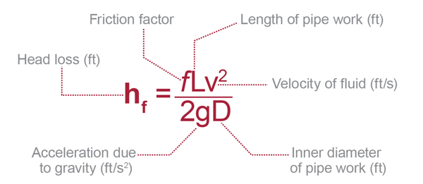
Each variable explained:
- Friction factor (f). This factor is dependent on the material. For example, a corroded and pitted material will inherently cause more friction than a smooth, new pipe.
- Length of pipe work (L). The longer the pipe run, the more energy is lost.
- Velocity of fluid (v). Faster fluid has more friction working against it.
- Acceleration due to gravity (g). A steeper angle will create less friction for the fluid.
- Inner diameter of pipe work (D). As diameter increases, the amount of pressure lost decreases.
What About Fittings?
Not included in the equation is how fittings create more energy losses for the system.
Friction losses through fittings are calculated using the equivalent length of straight pipe that causes the same friction loss as the corresponding fitting. Equivalent length of pipe refers to the length of straight pipe that causes the same friction loss as the corresponding fitting. Fittings can impact head loss, or the energy lost due to resistance against the fluid flow.
Many piping simulation programs neglect to adjust factors for plastics. If utilizing simulation software, designers should consider manually inputting the proper equivalent length and friction factors into the software for CPVC.
Below is the friction loss through fittings of Corzan® CPVC. Consult the fitting manufacturer’s literature for additional information.
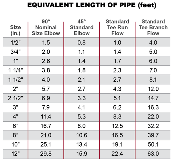
When calculating head loss using the equation provided above, the length (L) would include the length of the pipe line, plus the equivalent length of pipe corresponding to each fitting.
What About Valves and Strainers?
Valves and fittings can cause pressure drop in a piping system because they disrupt flow patterns. Compared to a straight pipe, valves and fittings have different geometries, sizes and impacts on direction of flow that must be accounted for in system design. Unlike fittings, each valve and strainer has a known flow coefficient, which is used to calculate the pressure drop (P) it causes when in the fully open position.
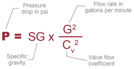
Each variable explained:
- Flow rate (G). Expressed in gallons per minutes, the greater the flow rate the more pressure will be lost through the valve or strainer.
- Valve flow coefficient (Cv). Determined through testing in accordance with industry specific standards with water.
- Specific gravity (SG). Because water’s specified gravity is 1.0, the specific gravity of a different fluid can be used to determine pressure drop with other fluids.
The flow coefficient for each type of valve and strainer can be found in the manufacturer’s literature.
CPVC and Head Loss through Fittings, Valves and Strainers
How each type of component affects friction loss varies only slightly across material and component types. But, over hundreds or thousands of feet of pipe, this can make a significant difference.
CPVC Advantages
The Hazen Williams C Factor, which compares the smoothness of different materials, is an important figure for maintaining fluid hydraulics. The higher the value, the smoother, more consistent the material surface is. At installation, CPVC has a C Factor of 150, which is mostly maintained throughout its life due to its inherent corrosion and scaling resistant. Alternatively, new stainless steel has a C Factor around 130, but can end up well below 100 after years of use.
As the pipe’s interior smoothness deteriorates, friction loss and related consumption costs will rise.
Another advantage of CPVC is that the inside diameter of its fittings matches the diameter of the pipe. In some other materials, the fitting inserted into the pipe is slightly narrower, creating an additional disruption to the flow and increased pressure loss at each fitting.
Considering CPVC Installation
The CPVC solvent cement joining process is simple and straightforward. Because each additional fitting creates more pressure loss, installers must still keep fittings to a minimum even when installing a CPVC system.
Need Specification or Design Support?
If you need help determining if CPVC is right for your process or if you need support designing the CPVC system, contact us. The Corzan Industrial Systems team is ready to answer your questions.