STRESS AND THE MODULUS OF ELASTICITY FOR CPVC PIPING VS. METAL
Industrial plants are challenging environments for piping systems, which are subject to extreme pressures, temperatures, stress and even impact. No matter what piping material is specified, piping system stresses must be considered and modifications made during system design to prevent issues that could require extensive repair or replacement.
Engineers must address factors such as expansion and contraction as part of the piping layout and support scheme. They must also consider the system’s working stress as it relates to piping layout supports, thermo-induced movement and how the modulus of elasticity is used to determine how the system will respond.
It is highly recommended that industrial facilities consider conducting stress analysis on piping systems to better understand stress points created through supporting the system. Regardless of what material is selected, improper piping layout that creates excessive stress on joints or excessive point loads are detrimental to any material, including steel. Proper support layout, selection and implementation can change performance tremendously, making over 30 years of performance life a reality.
Thermal Expansion and Contraction
All piping materials possess inherent thermal properties that affect their characteristics based on the amount of heat or cold they incur. Piping material typically expands when heat is applied and contracts during colder conditions.
Most thermoplastics have a coefficient of thermal expansion that is significantly higher than that of metals. The thermal expansion of a CPVC piping system subjected to a temperature change, therefore, can be significant, Generally, a total temperature change greater than 30°F (17°C) will require compensation for thermal expansion during piping system design.
Accounting for piping system expansion and contraction is always an excellent design practice. Unless the system is in a controlled environment, typical thermal cycling relative to the seasons usually creates the need to address expansion and contraction.
The expansion or contraction of thermoplastic piping may be calculated using the following formula:
Thermal Expansion Formula
ΔL = LpC ΔT
Where:
ΔL = Change in length due to change in temperature (in.)
Lp = Length of pipe (in.)
C = Coefficient of thermal expansion (in./in./°F)
= 3.4 x 10⁻⁵ in./in./°F for CPVC
ΔT = Change in temperature (°F)
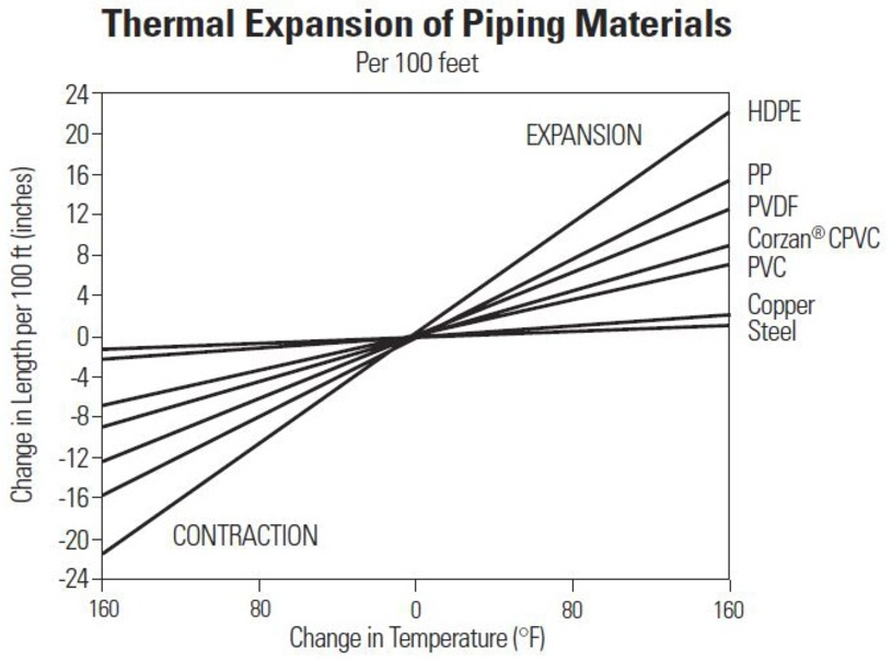
The following illustration shows the thermal expansion and contraction of Corzan® CPVC versus other common piping materials: It should be noted that Corzan CPVC’s coefficient of thermal expansion is very favorable compared to other non-metallic materials capable of handling 180° F temperatures.
Working Stress and the Modulus of Elasticity
Working stress is the maximum level of stress a material can be subjected to when in use. All piping material can withstand some degree of movement without sacrificing its structural integrity.
The modulus of elasticity is a measure of a material’s stiffness and its inherent ability to deform when stress is applied. Corzan CPVC has a very low modulus of elasticity, which means it has the flexibility to absorb the shock from a less severe impact and, to some extent, can bounce back to its original shape without any structural damage. Shock transferred to the connecting system will also be minimal.
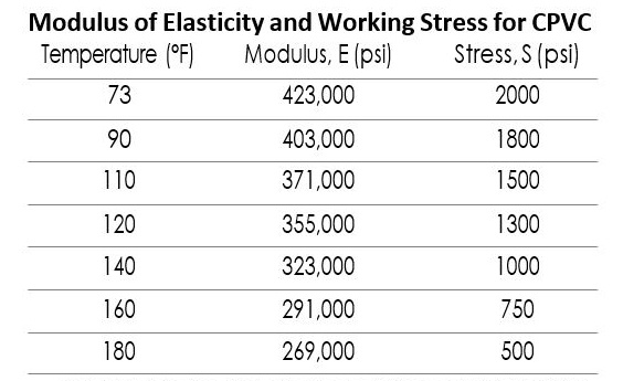
The following chart shows the modulus of elasticity and working stress for CPVC piping at various temperatures.

Metal piping–such as steel–has a high modulus of elasticity, which makes it very rigid. Depending on the type and intensity of the impact, metal piping such as copper is more likely to dent or crease, which can impede fluid flow. Small cracks may also form, weakening wall strength, limiting pressure capabilities and increasing corrosion concerns.
Designing for Expansion and Contraction
Linear expansion and contraction is the second greatest concern when designing piping systems and impacts both metallic and thermoplastic piping materials. If not addressed during piping system design, length fluctuation could lead to expensive pipe repairs and premature failure. This situation is exacerbated for industrial piping systems subjected to extreme temperatures and pressures.
While expansion and contraction are unavoidable, resulting problems can often be prevented by incorporating deflection mechanisms during design that allow for some degree of pipe movement to help prevent compressive stresses.
Expansion loops – This deflection mechanism is often the preferred choice among engineers and includes configuring a “U” in the middle of the pipe run, with the center of the U restrained with a bracket. Each end of the pipe run is set using a hanger or guide that allows the pipe to move back and forth. The opening of the U narrows as the pipe expands and the U opening widens during contraction.
Click on the image below to observe how the pipe opening moves.
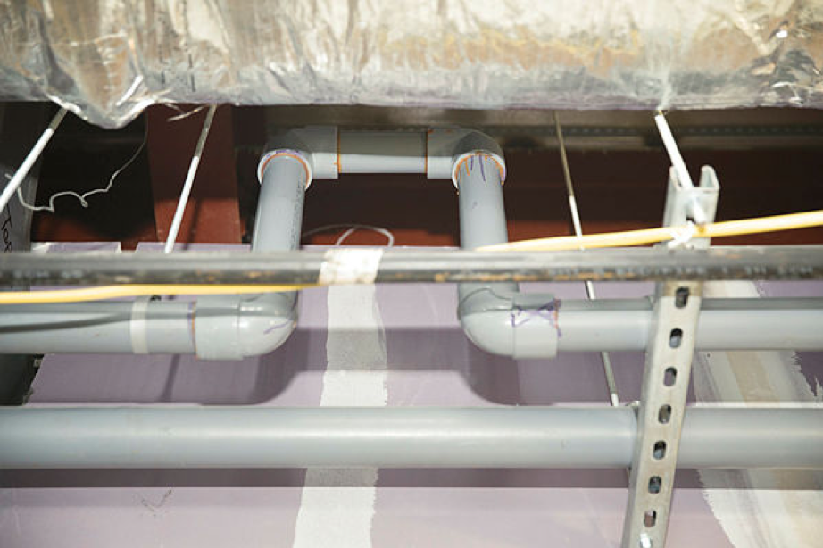
A critical part of a properly installed expansion loop is the placement of the restraint. It is essential that the piping layout design strategically utilize restraint hangers so that movement is controlled in the appropriate areas. For expansion loops, the restraint is placed in the base of the U as shown above. If you refer back to the photo at the beginning of this article, you will notice that the loop was installed without a restraint. If assistance is needed to better understand expansion and contraction, please contact your local Lubrizol subject matter expert.
Expansion offsets – This technique is generally employed when the piping needs to avoid a fixed structure. An offset is placed in the center of the pipe run, with each elbow allowing for some degree of deflection -- as does the vertical length of pipe. The end of each pipe run is established using hangers or guides positioned a certain distance from the elbow.
As the pipe expands, the top and bottom elbows push in and cause the vertical length to angle to the right. The vertical pipe will angle to the left during contraction. Click on the image below to see how the offset moves during expansion and contraction. It should be noted that proper movement for expansion and contraction will not be achieved if 45-degree fittings are used. Offset techniques require the use of 90-degree elbows to properly distribute the stress of expansion and contraction.
Change of direction -- The corner elbow and adjoining pipe at the end of the long run of pipe can facilitate some degree of movement. If the adjoining pipe is long enough, the engineer can place a hanger or guide a defined distance from the elbow to allow for both expansion and contraction. Click on the image below to observe how the corner elbow and adjoining pipe at the end of the long run of pipe facilitate movement. Note that the distance of the L is critical so as not to over stress the elbow in the change of direction.
Corzan CPVC Pipe Expansion Calculator helps engineers account for Corzan CPVC’s linear expansion and design around compress stress concerns.
Installing Corzan CPVC
Corzan CPVC piping, of course, is not steel and should not be installed like steel. Proper installation is critical to the performance of all Corzan piping systems, with engineers compensating for stresses and thermal expansion and contraction as part of their pipe layout and support scheme. ASME B31.3 bonder qualified installers should be the only people who handle the piping system. Proper solvent cementing is the most common issue encountered during CPVC system installation. Proper training and understanding can help prevent any issues.
Corzan CPVC has proven its ability to withstand the ongoing challenges of the world’s harshest industrial environments for over 60 years. Contact a Corzan engineering expert or one of our partner manufacturers for engineering guidelines to specify a reliable and cost-effective piping system or to schedule a free process suitability review and technical assessment.


